![]()
|
|
|
|
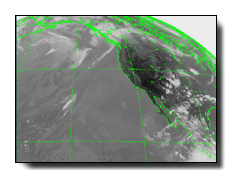
Geostationary weather satellite reception and imaging.

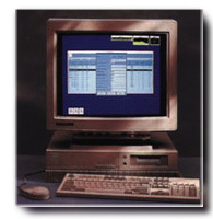
Global Imaging's EarthTracer is a fully integrated, direct readout ground station for the reception and processing of data from geostationary spacecraft including NOAA GOES I - M satellites, European Meteosat, and Japanese GMS. The EarthTracer ground station includes a powerful Hewlett Packard UNIX computer, software for automated, uninterrupted data collection, data processing software, and a collection of general image processing and display functions. Earth Tracer data processing software includes functions for GOES GVAR and AAA format processing, Meteosat A and B processing, and GMS S-VISSR processing.

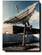
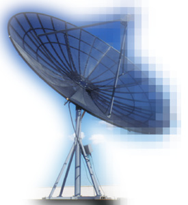
Each EarthTracer ground station includes an aluminum frame, parabolic mesh antenna, pedestal, low noise amplifier, receiver, and bit and frame synchronizer. Antennas come standard in sizes ranging from 12' to 16'. The position of the antenna is controlled by a specially constructed actuator. The positioner receives its instructions from a remote controller with a digital display.
EarthTracer bit and frame synchronizers offer SCSI compatibility, two satellite inputs, and connect directly onto the SCSI chain of Hewlett Packard UNIX scientific workstations. Data is sectorized in real time by the workstation software and sent directly to the workstation disk for further processing.
Hewlett Packard offers a wide variety of workstation choices-all deliver exceptional floating point/cost performance and include numerous graphics options. Hewlett Packard scientific workkstations will meet the needs of even the most computationally intensive application.
The EarthTracer ground station is completely automatic. System managers control the automatic operation of the system using Global Imaging's Automatic Satellite Acquisition and Processing Manager (ASAPMGR) windows software. ASAPMGR software allows the system manager to specify completely the sectors to be extracted from each data transmission.
Sectors are extracted from the data telemetry and stored on the workstation disk in real time. Sectors are defined by specifying the center latitude/longitude (or the satellite line and sample coordinates), the extent of the sector (the number of lines and number of samples in the sector), the channel number of the data to be extracted, the data sub-sampling in integer increments from 1 to 128, and the percent of area coverage of the sector. Sectors are created from all possible modes of data transmission including rapid scan and other special modes of transmission.
Global Imaging EarthTracer software allows sectors to overlap. EarthTracer software accommodates simultaneous ingestion of multiple sectors at multiple resolutions. Reduced resolution and full resolution sectors can be ingested simultaneously. Reduced resolution sectors can be of any size and location up to and including the full earth scan. Calibration and navigation information is extracted and stored for each sector. EarthTracer systems provide for the simultaneous extraction of up to 200 sectors.
Sectors can be written in Global Imaging's proprietary file format or optionally in McIDAS-X compatible format. Global Imaging offers an ingest option which provides for seamless compatibility with McIDAS X viewing and processing software. EarthTracer software allows the user to specify the directory and area numbers for the ingested sectors and the number of sequential images to be extracted per sector.
Each EarthTracer ground station includes a complete set of data processing software for precision navigation, radiometric calibration, and interpolation to standard map projections.
Cloud Top Heights-The infrared data are used, in conjunction with other parameters, to estimate the temperatures of the cloud tops. Cloud top temperatures can be combined with radiosonde data and conventional temperature analyses using an interactive computer process to determine the height of the tops of clouds.
Sea Surface Thermal Patterns-The infrared channels on GVAR and GMS-5 allow accurate water vapor correction, accurate cloud detection, and a true multi-channel sea surface temperature. These data are extremely useful for hemispherical maps of sea surface temperature. Examples of features which can be detected include the Gulf Stream and its major meanders and eddies, the Gulf of Mexico Loop Current, equatorial ocean circulation, and the Kuroshio flow.
Quantitative Precipitation Estimates-The new GVAR and GMS-5 water vapor channels, combined with visible and infrared imagery, will prove especially useful for quantitative precipitation estimates. A particular application of meteorological interest is the estimation of the amount of precipitation coming from convective storm systems and hurricanes.
Weather Warnings-Imagery from geostationary satellites are used by the National Weather Service to provide weather warnings and forecasts. The National Hurricane Center (NHC) and local forecast offices use sequential GOES images collected using EarthTracer ground stations to identify, track and estimate the intensity of developing tropical storms and hurricanes for an area that stretches across the Atlantic Ocean to west of the Hawaiian Islands in the Pacific. Satellite imagery is often the only source of real-time information across this vast oceanic area making it of particular interest to operational fishing industries.
Sea Fogs-Modern methods of image segmentation can be used to detect fog at sea. This is especially important in the heavy ship trafficking lanes and in coastal regions.
Calculation of the Earth's Energy Balance-The improved bit resolution of GVAR data over historical GOES AAA data makes them much more quantitatively useful for the computation of the earth's energy balance.
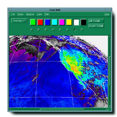
For displaying and interactively manipulating graphics and image data, Global Imaging provides FOCUS software with each ground station. FOCUS software consists of over 100 functions and includes commands for altering image contrast and brightness, for overlaying latitude longitude grids and for automatically drawing coastlines and bathymetric and elevation contours from on-line worldwide databases. FOCUS provides for eight independent graphic overlay planes and pseudocolor and monochrome lookup tables. Operators can also use FOCUS to pan and zoom image data, annotate images, and play animation loops. FOCUS is Motif-based and thus is fully compliant with industry-accepted graphical and data transmission standards.
Global Imaging conducts site surveys and offers installation, on-site training, and follow-on maintenance standard. Optional software subscription services, which insure that your software is never out of date, and phone-in consultation services are also available. The EarthTracer is warranted for one year after installation. Extended warranty on all hardware and software is also available at the time of purchase.

The following specifications define a basic GVAR EarthTracer ground station and serve as a model for other EarthTracer systems. Standard hardware operates from 110-120 VAC, 50-60 Hz power. 220 VAC, 50-60 Hz operation options are also available.
IF Input 137.0 MHz Sweep Range + 90 Khz Acquisition Sensitivity Less than 90 dbm minimum Frequency Selection Single frequency Output NRZ (low impedance output capable of driving 100 ft of cable)
Input Compatibility NRZ 2.111 MB/sec Input Voltage Range 0.25 to 10.0 Vpp Input Impedance 100 ohms Tracking Range Auto tracking Outputs NRZ, 0° and 90° clock Sync Threshold vs. Noise Synchronization is maintained down to a S/N of 6dB. Sync vs. Jitter noise Synchronization is maintained with jitter amplitudes less than 1% of the bit rate occurring at any rate of change. Sync vs. Acquisition Average acquisition time for an input time signal within the loop bandwidth is 200 bit periods for NRZ. Resolution of Clock ambiguity Resolves clock ambiguity after 16 data transitions. Loop synchronization is then held indefinitely as long as the noise or jitter threshold of the loop is not exceeded. Bit Error Rate vs. Noise Within 2 dB of theoretical down to S/N ratios of 6 dB.
Antenna type Aluminum Frame Parabolic Reflector Gain 36.2 dB at 1700 MHz Diameter 4.8 meter(l6 ft) 3 dB Beamwidth 3.1° at 1700 MHz LNA Noise Temperature 60K (Kelvin) typical System Noise Temp Better then 100 Kelvin typical System G/T 16.2 dB/K typical Positioner Movement 90° minimum Limit switch protection Full override 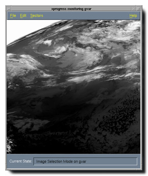
RF Input 1685.7 Mhz IF Output 137.0 MHz Cable Length 360 ft. maximum (RG-213 or equivalent) Interdigital Filter 4 pole Chebycheff, 2% pass band loss less than 1 dB
Please contact Michael Guberek for more information on Global Imaging's EarthTracer for tracking geosynchronous spacecraft.


201 Lomas Santa Fe Drive, Suite 380
Solana Beach, CA 92075
(858) 481-5750
(858) 481-5794 (Fax)
E-mail mguberek@globalimaging.com
|
|